IT Systems are distribution systems which are preferred less compared to Grounded Systems at Industrial Institutions. The main reason for this is to maintain the installation integrity. But due to the electrical security that it provides, IT Systems are preferred to be used at the supply of the critical divisions in the Institutions. The main difference that discriminates IT systems from Grounded Systems (PN or PP) is the non-presence of the Institution Grounding. This is obtained by isolation transformer and each load that is connected to this distribution system has its own individual grounding. These systems are mainly used in the supply of the rooms like surgery rooms at the hospitals.
In the event of first isolation failure, energy blackout does not happen. The security equipment controls the system continuously therefore the energy blackout is prevented
The Medical Devices continue their normal operations. Fault Currents are reduced to non-critical levels which means the leakage current that is present within the room is reduced from mA levels to ?A levels.
A possible inconvenience in the surgery room is prevented where energy is reserved and blackout does not happen.
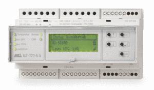
This is a multi-functional device produced for electrical control at Isolation Systems. The following parameters can be observed with it; The insulation resistance of a one or multiple-phase (for a maximum of 3) AC 230 V IT system The insulation resistance of an AC 24 V IT system (OP lamps with 1 or 2, one-phase circuits) The load current of one or multiple phase transformers up to 8 kVA (through The temperature of the transformer (through a PTC or break contact) It monitors all measuring lines. Its built in full graphics display allows you intuitive menu led operation while providing you with the details of all operating and fault messages. You can also edit all of the parameterisable unit settings with a menu system and the parameters are stored in the non-volatile Eeprom.
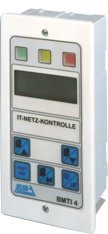
This terminal is used for displaying operating & fault signals in the IT networks in the areas used for medical purposes in conformity with DIN VDE 0100 T710- 2002:11. The unit also has a disinfection friendly foil surface. The unit's intuitive menu control makes it easy to use. It can also create individualized alarm texts with configuration software, making it possible to switch up other trades. The large scale fully graphic display is lighted, allowing a clearly structured display of the information from several systems. Large programmable multifunction buttons enable you to control the display. Manual test and service functions can be initiated on the system bus. The electrical unit's technical data and operating states are transmitted through the CAN bus. It also shows the operating states on the (red, green and yellow) LED's in addition to the text display
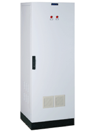
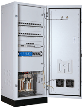
Isolation Transformers are the main devices of Isolated Systems. With the help of isolation transformer, the supplied room is isolated from the Grounded System. Consequently the leakage current within the room is reduced from mA levels to ?A levels. Besides there is also one advantage that is; in case of initial Phase-Ground short circuit, there shall be no blackout. The hospital isolation transformers that supply the mission critical locations shall have the following important electrical features ; The nominal power of the transformer shall be maximum 10 kVA. It shall be Single Phase. In case of it being 3 Phase then the L-L Voltage shall be 250 VAC. condition. No Load Condition Current shall comply the Io < % 3 condition. The Initial Current value shall be less then 8In.
The IFS-710-W6 is installed in distribution boards (DIN 43871) on top-hat rails (DIN EN 60715). Assembly, connection and start-up of the IFS-710-W6 may only be carried out by qualified electricians. All relevant safety regulations and standards have to be observed. The IFS-710-W6 is connected in accordance with the connection diagram and the individual connection specifications (see chapter 3). Observe the technical specifications of the devic. A separate documentation is provided with information about the CAN bus. The device automatically monitors all internal functions and the state of the communication interface. Regular maintenance is therefore not required.
Insulation Error Analysis System MODEL: IFS-710-W6